
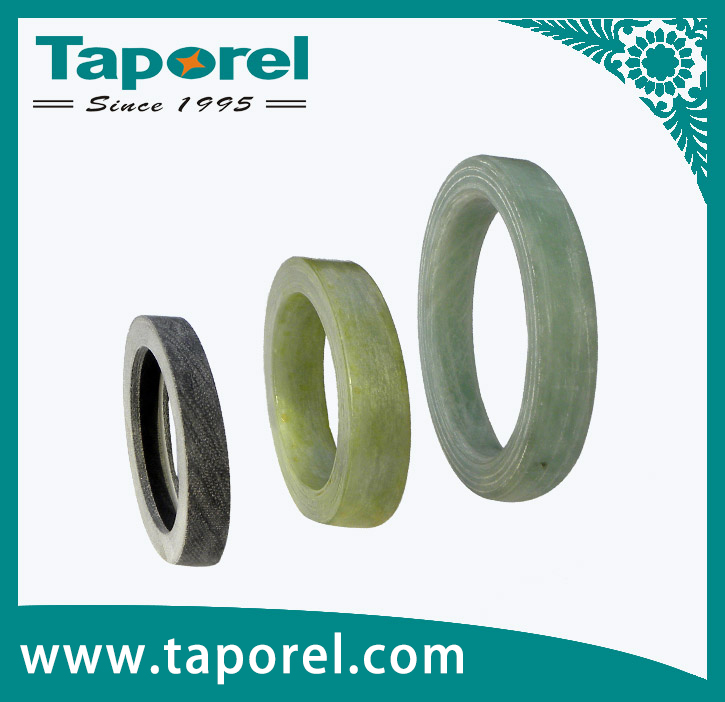
Insulating Rings & End Rings for Dry-type Transformer
1. Product Introduction
The dry-type transformer insulation ring/end ring is manufactured from epoxy fiberglass-wound tubes. The epoxy fiberglass-wound tube is an insulating product made by impregnating alkali-free E-glass fiber with epoxy resin, followed by heating and curing. The winding angle can be adjusted from 10° to 65° (adjustable according to your requirements to achieve the desired mechanical properties). We can also produce tubes with thermal classes B, F, and H as per customer requirements.
Our company offers a full range of fiberglass-wound tube specifications (please contact our sales department for detailed specification sheets). These products are specifically developed for high-voltage electrical equipment components such as 110KV–1000KV composite hollow insulators, reactors, arresters, fuses, instrument transformers, on-load tap changers, transformers, and more. All product performance parameters meet IEC standard requirements.
2. Product Features
(1) Temperature resistance: 120°C, 155°C, 180°C, 200°C and above.
(2) Color: Primarily light green; custom colors are available upon request.
(3) Voltage rating: 10KV – 1000KV.
Diameter range: Inner diameter from 5 mm to 1 meter.
Length range: From 10 mm to 12 meters.
Thickness range: Minimum 0.5 mm.
(4) The inner and outer diameters of the fiberglass tubes can be specially treated according to customer requirements.
(5) Tube specifications depend on inner diameter and length dimensions. For sizes not available in our standard mold inventory, we can customize molds based on your order quantity.
(6) When placing an order, please specify the model and type, and provide drawings as well as relevant technical requirements.
3. Product Parameters
| No. | Item Name | Unit | Index |
| 1 | Density | g/cm³ | ≥1.92 |
| 2 | Flexural Strength | MPa | ≥320 |
| 3 | Compressive Strength | MPa | ≥200 |
| 4 | Shear Strength | MPa | ≥32 |
| 5 | Dielectric Dissipation Factor | — | |
| 6 | Dielectric Constant | — | 3–6 |
| 7 | Volume Resistivity Under normal condition After water immersion |
Ω·m | ≥1.0×10¹¹≥1.0×10⁹ |
| 8 | Parallel Layer Insulation Resistance Under normal condition After water immersion |
Ω | ≥1.0×10¹¹≥1.0×10⁹ |
| 9 | Surface Withstand Voltage (Withstand test in air for 1 min, gap 30 mm) |
kV | 14 |
| 10 | Vertical Layer Withstand Voltage, δ≤3 mm(Withstand test in transformer oil at 90±2℃ for 5 min) |
kV | 18 / 20 |
| 11 | Parallel Layer Withstand Voltage (Withstand test in transformer oil at 90±2℃ for 5 min, gap 25 mm) |
kV | ≥25 / ≥50 / ≥75 |
| 12 | Insulation Resistance | MΩ | ≥5×10⁴ |
| 13 | Power Frequency Withstand Voltage for on-load tap-changer oil chamber, earth clearance (Withstand test in transformer oil, 100 mm, 5 min; phase distance subject to customer’s technical requirements) |
kV | ≥85 |